Gary Anderson: How I'd remove F1 2026's biggest problem
When these new Formula 1 regulations for 2026 were introduced, many, including myself, questioned how it was all going to work.
Until the end of 2025, we had a power split of roughly 84% internal combustion engine and 16% electrical, but for 2026, it is now theoretically a 50/50 split.
On top of that, the MGU-H is gone. Under the previous regulations, this was used to control the turbo speed and could be used both to spin up the turbo to reduce lag, or hold it back to maintain the boost pressure and turbo speed.
Doing the latter was also used to harvest energy, which could either be used immediately or to recharge the battery pack.
As pre-season testing showed, it is not easy to manage the electrical output versus the electrical input and allow the driver to actually be a racing driver. Far too much driver management is required, especially over a race distance. Worse still, the driver even needs to manage it over one lap in qualifying.
Some of them have been vocal about the problems, and others more diplomatic, but in general, they are all unhappy about having to do anything more than just drive the car flat out.
To explain it simply, it’s a bit like balancing your income with your expenditure. However, it’s really the other way around, balancing your expenditure against your income. If you go about it that way and spend too much, then all you can do is go out and find a higher-paid job, or get a second job. It’s very easy to say but very difficult to do.
So here are my proposals to potentially balance the F1 books and remove the need for so much driver management by having a simple electrical power distribution map that is managed by the standard engine control unit (ECU) used by all the teams.
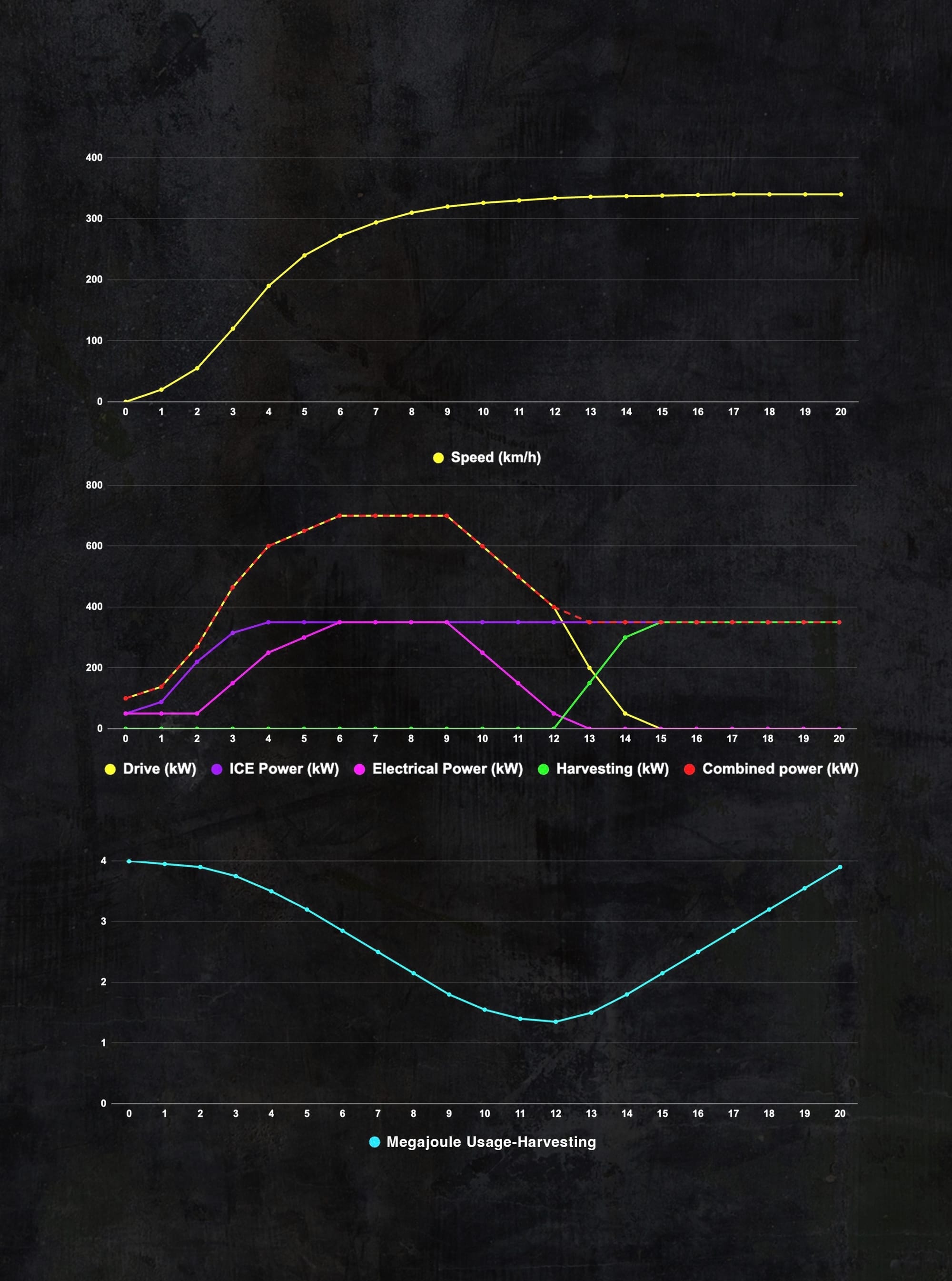
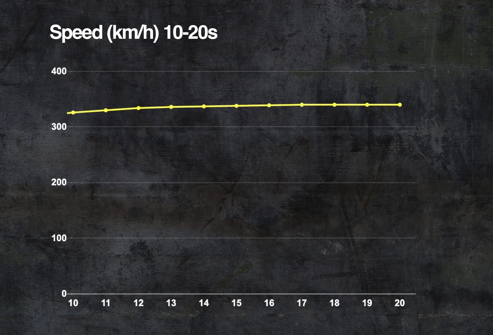
This three-part graph shows the output and input over a 20-second range. Basically, all that is from zero speed up to 340km/h or what for a given downforce level, would be terminal velocity. The first graph shows the speed in the yellow trace. The second shows the drive (as in the power that is being used to push the car along, discounting anything being used to charge the battery), the power of both the V6 engine and the MGU-K (both in kilowatts for consistency, with 1kW equalling 1.341bhp), the harvesting level and the combined power of the V6 and the MGU-K.
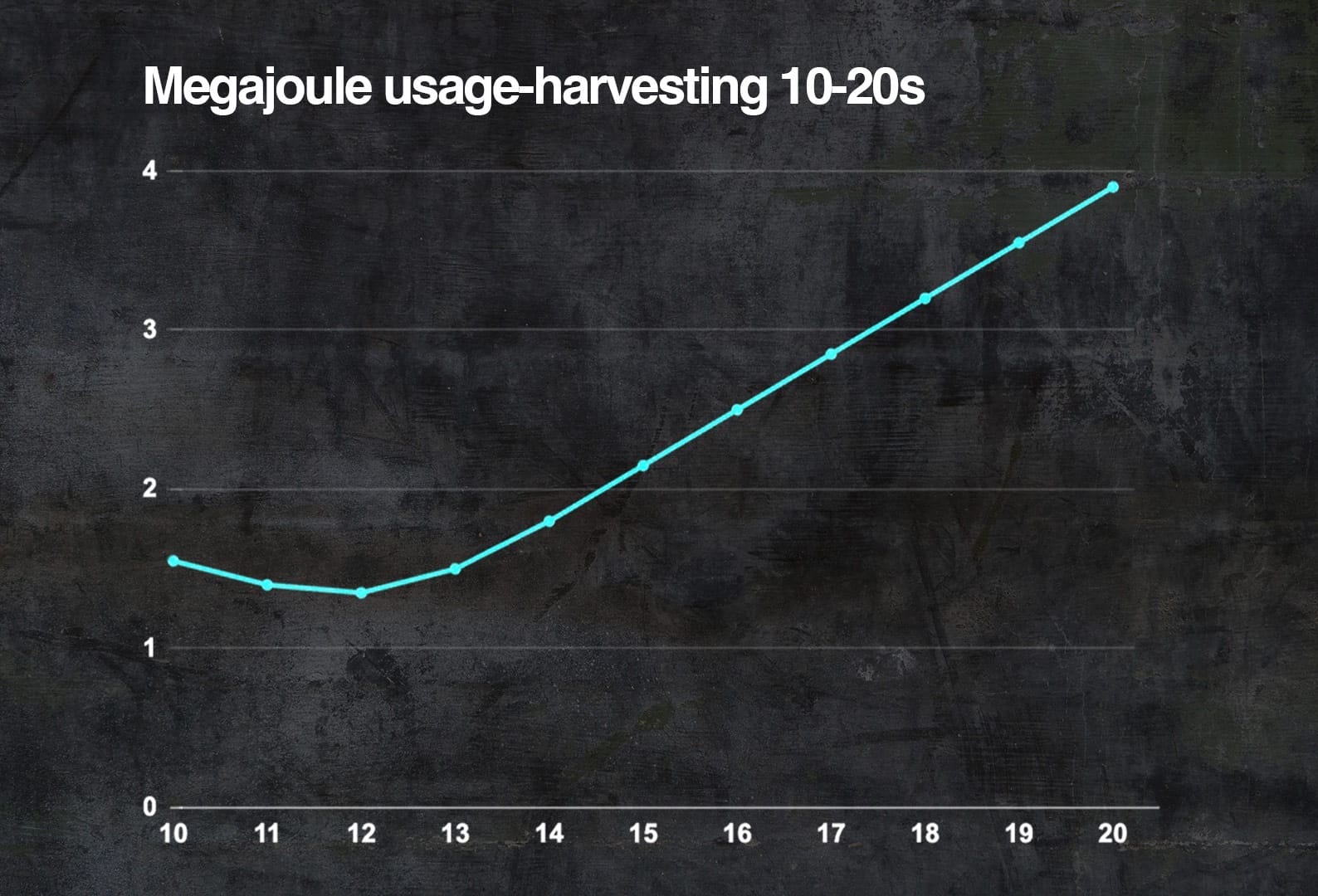
In the bottom graph, it shows the amount of megajoules stored in the battery as it is first spent from the maximum of 4mJ and then harvested.
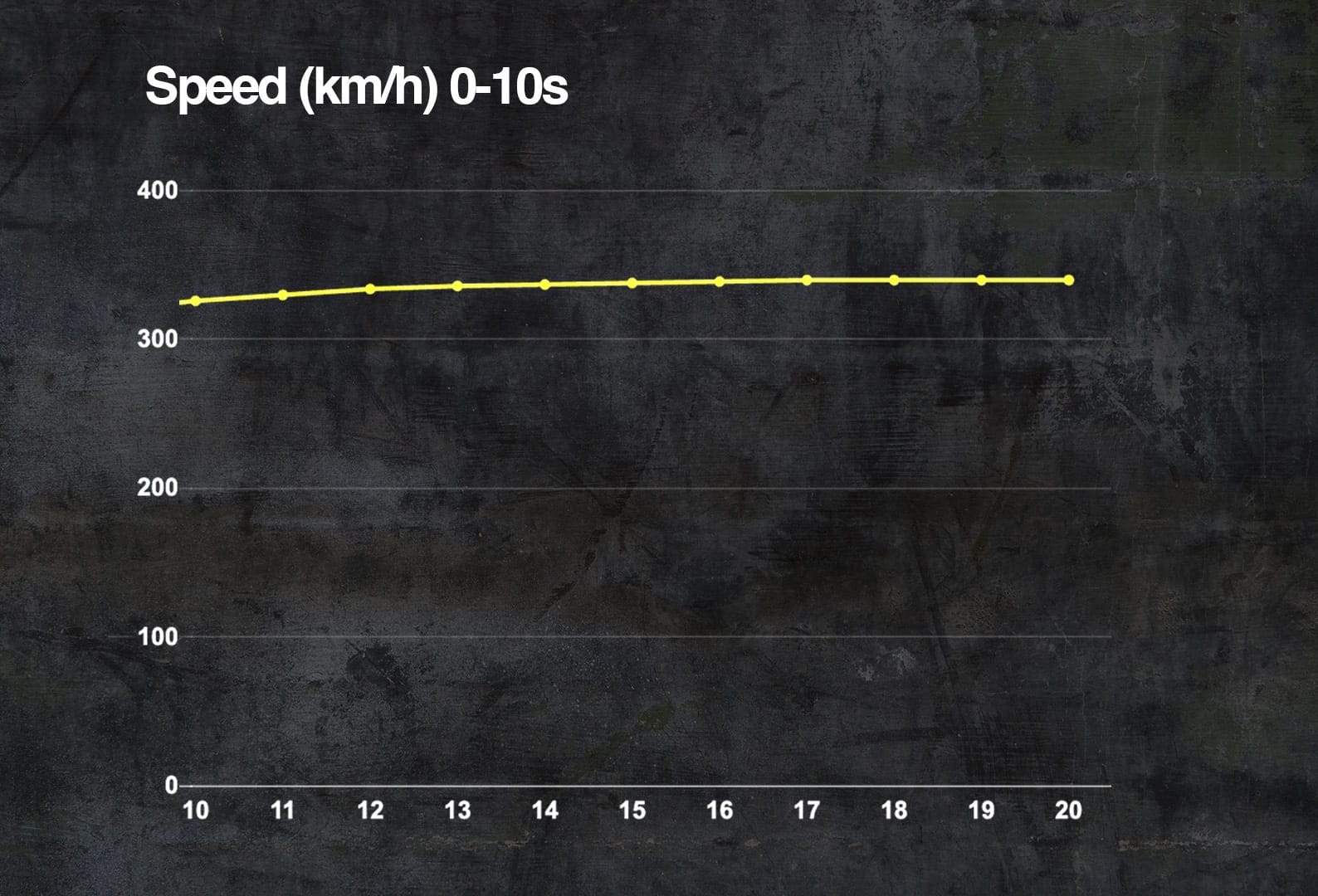
Obviously, there are many occasions during a lap where the driver comes on and off the throttle and/or presses the brake pedal, so it’s not quite as simple as a flat-out run from zero speed to 340km/h. I will deal with those in two units: zero to 10 seconds to cover the starts and slow-medium speed corners and 11 - 20 seconds to cover mid-to-high-speed corners and the high-speed harvesting.
My main objective is to balance the electrical output and input whilst still achieving that promised objective of a 50/50 power split of 350kW, albeit for only a few seconds.
Basically, you are allowed to use up to 4MJ from the battery pack in any one hit, that 4MJ gives you your maximum of 350kW for a total of roughly 11.5 seconds. But what you take out with each hit, you need to put back ready for the next time. That’s what is called harvesting.
In an earlier article, we put together an average circuit requirement, so that is where this output and input need to balance out. With the lower grip of the 2026 cars, I have created a second table and adjusted the numbers to suit. For the outliers like Monza or Monaco, that output requirement can just be changed by a percentage of the average circuit requirements.
Average circuit 2025
Laptime 1m23.687s = (5192 metres)
Full torque requested 60.25s = (72% of lap).
Braking 13.39s = (16% of lap).
Part brake/throttle 10.87s = (13% of lap).
Lower grip 2026 cars
Laptime 1m26.000s = (5192 meters)
Full torque requested = 58s (67% of lap)
Braking 15s = (17s of lap)
Part brake/throttle = (13s of lap)
This graph is over 20 seconds, so if a circuit had four equal sections, it would more or less cover a complete lap. That 20 seconds is also about the longest full throttle request we see over any current circuit and is more than most other full throttle applications.
The electrical output versus electrical input is all we are really interested in, but that needs to be dependent on the throttle pedal, brake pedal position, speed and pit limiter. So from zero front wheel speed, which basically is off the startline, a pitstop, or even a spin, there is a minimum of 50kW of torque available.
When the car gets to more than 50km/h (fastest front wheel speed) and the throttle pedal gets to above 95%, that kicks off a torque ramp that gradually increases the deployment power. The other restriction here would be that the pit limiter has to be switched off.
The torque ramp increases by XkW steps per second until the car either reaches a predetermined speed or the driver reduces the throttle pedal position to less than 95% and/or applies brake pressure above, say, five bar. I am using time for this ramp as it eliminates any problems from front wheel locking under braking, which is something we are going to see a lot of this year.
With these figures and the harvesting not coming into play until 340km/h, which becomes the notional top speed as indicated by the yellow speed trace flattening out, we get to a maximum electrical torque output of 350kW for six seconds after a standing start. However, over the 20 seconds, the total electrical consumption is 135kW and with that ramp, you have used 2.65Mj of your allowable 4.0Mj.
This leaves enough in the battery pack for what I call my overtake mode. I’ll explain that a bit more later.
Again, using a simple harvesting ramp that kicks in at 320km/h and manages how dramatically you can back the power off by ramping the output down and harvesting up over five seconds to reduce the risk of instant deceleration at high speed on this graph, we more or less balance that electrical output of 2.65Mj with an electrical input of 2.55Mj.
Ramping the output torque down to zero before the harvesting ramps up will reduce the closing speed of any car behind.
Yes, five seconds is a long time in F1 and this can be very easily reduced, but in my opinion it’s better to start on the safe side, the last thing we need is an aeroplane accident between two cars in excess of 300kph.
But it’s not all about a flat-out zero to terminal velocity drag strip, a lot can happen on the way.
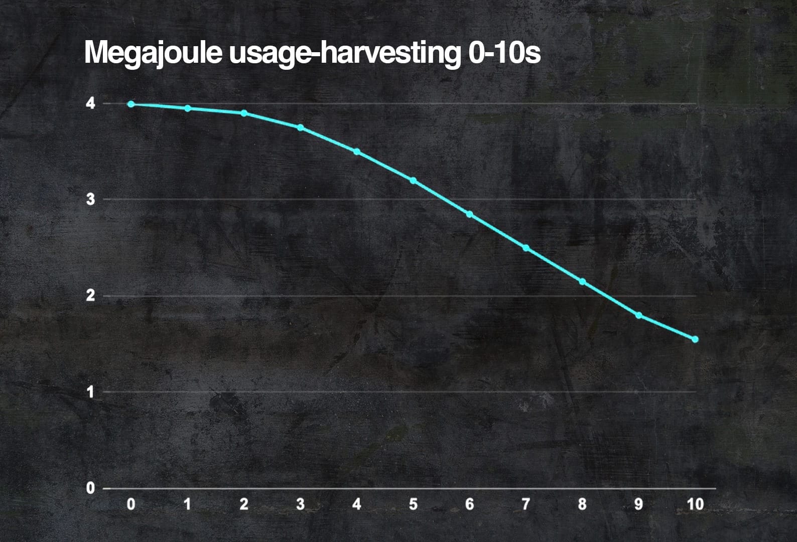
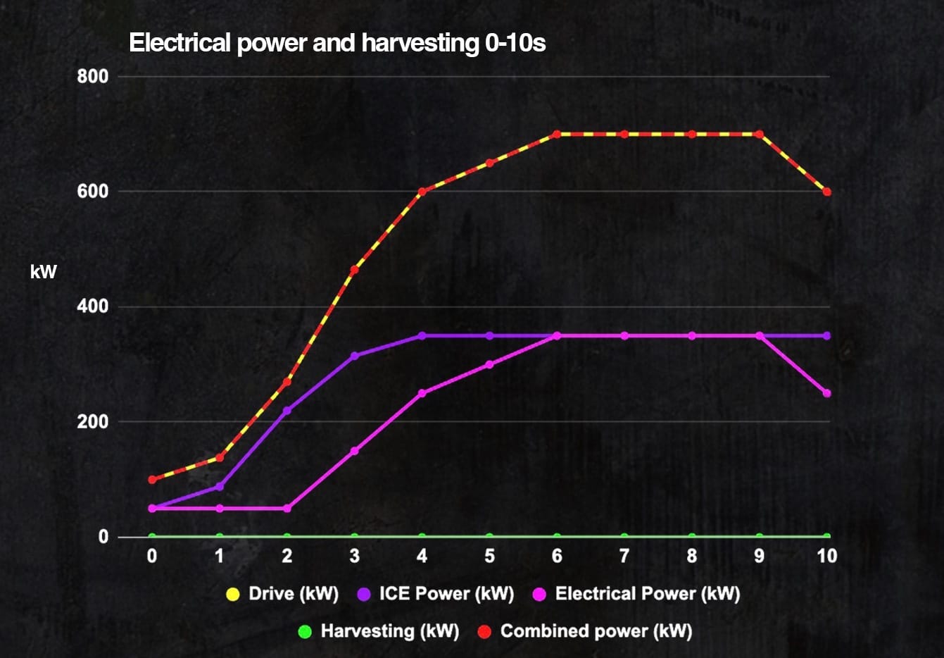
Looking in more detail at the zero to 10 second section, the 50kW flat rate electrical output is to reduce the turbo spin-up problems that have now become evident with the removal of the MGU-H. The last thing we need is to witness a major start-line incident when a car stalls.
While 50kW is not much, with the MGU-K being directly connected to the PU, it will stop it from going into anti-stall and get the car off the line and rolling in the correct direction.
During any period from zero speed up to 50km/h (fastest front wheel speed), the electrical output will stay at 50kW, which covers recovering from a spin or exiting from a pitstop. In the latter scenario, the ramp wouldn’t kick in until the pit limiter was switched off, and it would then kick in at the level relative to the speed at which the limiter is switched off at. Similarly, when you enter the pits and switch on the limiter, the electrical power would reduce to 50kW.
As for slowing into corners, the throttle position and brake pressure would be the dominant commands; with either of these state changes, the driver wants to slow down, so the harvesting ramp comes into play. When the driver comes off the brake pedal to less than five bar and back on the throttle to more than 95%, then they want to go faster, and the torque ramp kicks back in at the relevant level for the speed they are travelling at. This covers most slow and medium speed corners.
If, for any reason, you have to take action to avoid another car or a mongoose crossing the track, then that’s just the luck of the draw. If you have to have a mongoose land in your lap, then it’s better to be going slower!
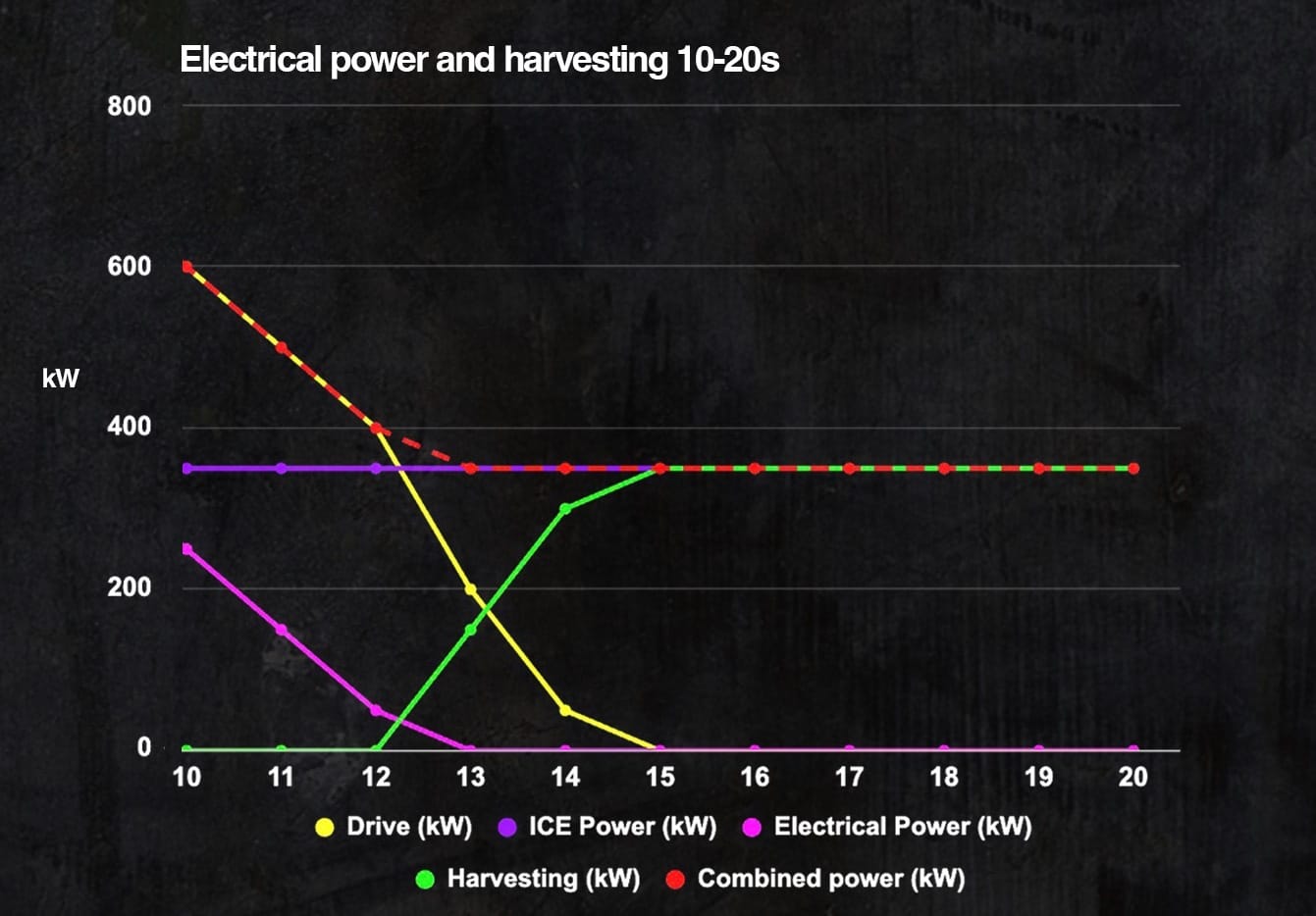
It’s basically the same as with the zero-to-10-second graph. This 11 to 20 second section covers most medium and high speed corners and the end-of-straight harvesting in more detail. For cornering, the same throttle/brake pedal position change relates to the driver wanting to slow down or speed up. Also, when the car gets to a certain speed, the harvesting ramp sets in.
What we need to remember is that with one motor, the MGU-K, you can’t apply power and harvest at the same time; it’s either one or the other.
Having the corner mode and the straight mode drag reduction available is the same for everyone, the triggers could be the same, throttle (over 95%) and brake pressure (less than 5bar). These triggers would define track conditions, in reality, it only affects the overall top speed of the cars, but at least it is reasonably visible for us viewers.
As I alluded to earlier you could also use this reduction in torque output as a torque increase overtake button, which could be used anywhere when low drag mode is in operation and you are within a second of the car ahead of you at the pre-defined track positions. These torque output and harvesting ramps could be adjusted simply to leave a minimum of 1MJ in the battery pack for use as that overtake button over the lap, following detection of being within one second of the car in front. It could be used anywhere over the lap as long as the car is in low drag mode.
So all of that, with probably a few numbers changed from circuit simulation, could be managed within the standard ECU, leaving the driver to do what they are paid for and wring the car's neck.
One other thing I would like to point out is the need for the drivers to use excessive engine revs, roughly 11000rpm on the grid and during pitstops to get the turbo speed to a reasonable level to produce the power to get the car away from a standstill.
To achieve those revs with no load on the engine, it would probably take a maximum of 5% throttle request, which would be nowhere near enough gas flow to get the turbo up to speed. So, to achieve that required gas flow, the drivers are putting the MGU-K into full recharge mode. This allows them to open the throttle much more, probably in excess of 50%, which increases the gas flow spinning the turbo.
To sum that all up, for those few seconds sitting on the grid, you have probably got the most expensive and inefficient generator in existence, plus that very short high-rate input into the battery pack will generate huge heat and management problems. And, more worryingly, if something goes wrong with the MGU-K control, you will probably end up with the engine going hard onto the rev limiter, or with nuts, bolts, pistons and con-rods spread all over the grid.
Hopefully, the shock of all that happening suddenly wouldn’t surprise the driver enough to unintentionally release the clutch. If they did, then the consequences could be much more dramatic than a bit of an oil spill.